|
|
|
Kaiser-Willys/Omix Ada 947348 Turn Signal Switch |
Post Reply 
|
| Author | |
duffer 
Member 

Joined: 02 Feb. 2012 Location: Bozeman, MT Status: Offline Points: 1086 |
 Post Options Post Options
") Thanks(0) Thanks(0)
 Quote Reply Quote Reply
 Topic: Kaiser-Willys/Omix Ada 947348 Turn Signal Switch Topic: Kaiser-Willys/Omix Ada 947348 Turn Signal SwitchPosted: 25 June 2019 at 2:11am |
|
I ordered one of these on-line from K-W about a month back.
In the interest of full disclosure, the installation was in my Polaris 900 Trail, but in all aspects, this was no different than any 12V negative ground system. So, after welding up a custom aluminum bracket (the Polaris tilt column has no place for the hose clamp mount provided), running new lamp wires to all four corners, and hooking up the leads as per the above diagram, did it work? Of course not. The only thing that functioned was the internal indicator lamp. There was nominally zero resistance between the lamp leads and that black ground wire in all positions. I didn't have much success with the last attempted return to K-W so I just removed it and tossed it on the bench, re-drilled my bracket, and installed one of the Spartan units I had hanging on the shop wall. After minor re-wiring for the 3 pin flasher unit-success. But no flashers. I then proceeded to disassemble the Omix unit and it was
more than obvious what the problems were.
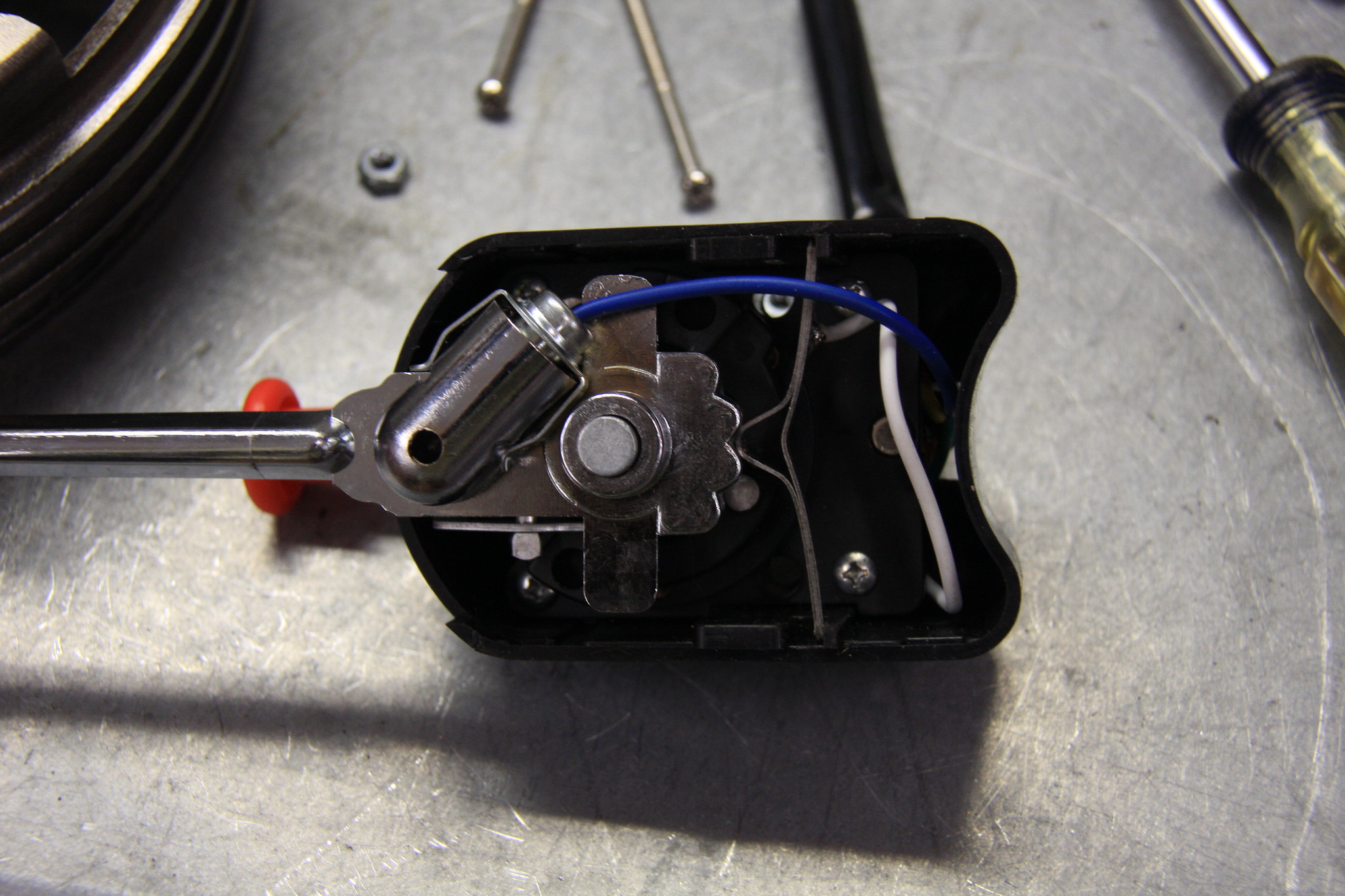
With the top cover off, you can see where the only connection to the
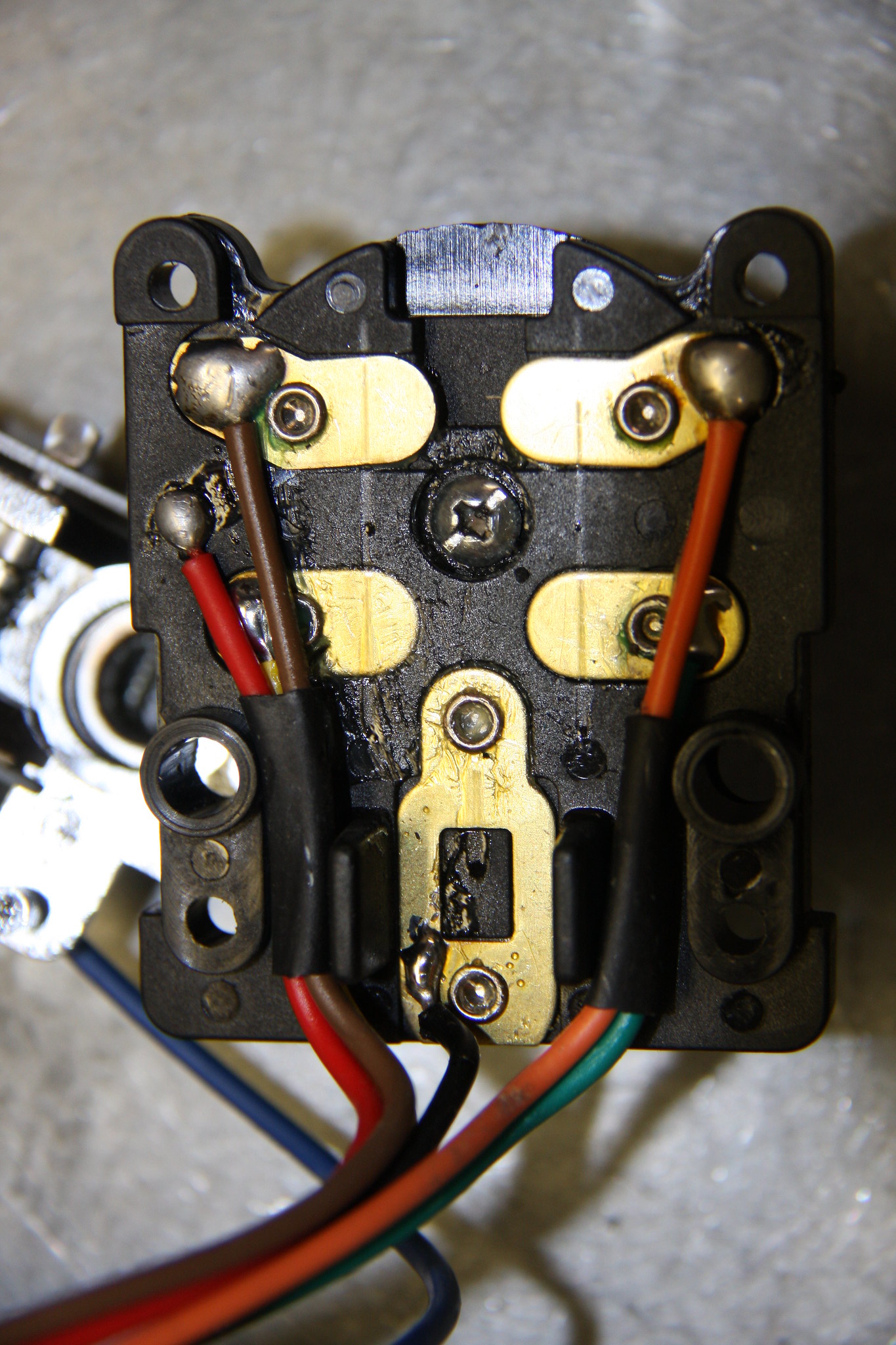
blue wire from the flasher unit is: the internal indicator lamp. The black ground wire connection? Well that is connected to the contact plate
for all four lamp leads (yellow, green, orange, and brown). Nominal resistance indeed. It should be noted that the ONLY thing in this unit that actually requires a ground is the internal indicator bulb. The good news? You can make this unit functional if you want to spend a little time on it. This is nothing other than a make-break rotary switch with an additional slider for the flasher function that makes contact with all four lamp leads. Of the input leads, only the red wire to the brake light switch is correctly wired. The black wire can be de-soldered from the above plate, spliced and connected to the internal white wire's connection to the wand spring detent or directly to the lamp. The white wire should be completely removed. The blue wire, previously attached to the internal indicator lamp needs to be moved to the location where the black wire was originally attached.
The two rotary wipers are concentric. The outer ring controls the brake light/turn signal
interaction and again, needs no modification.
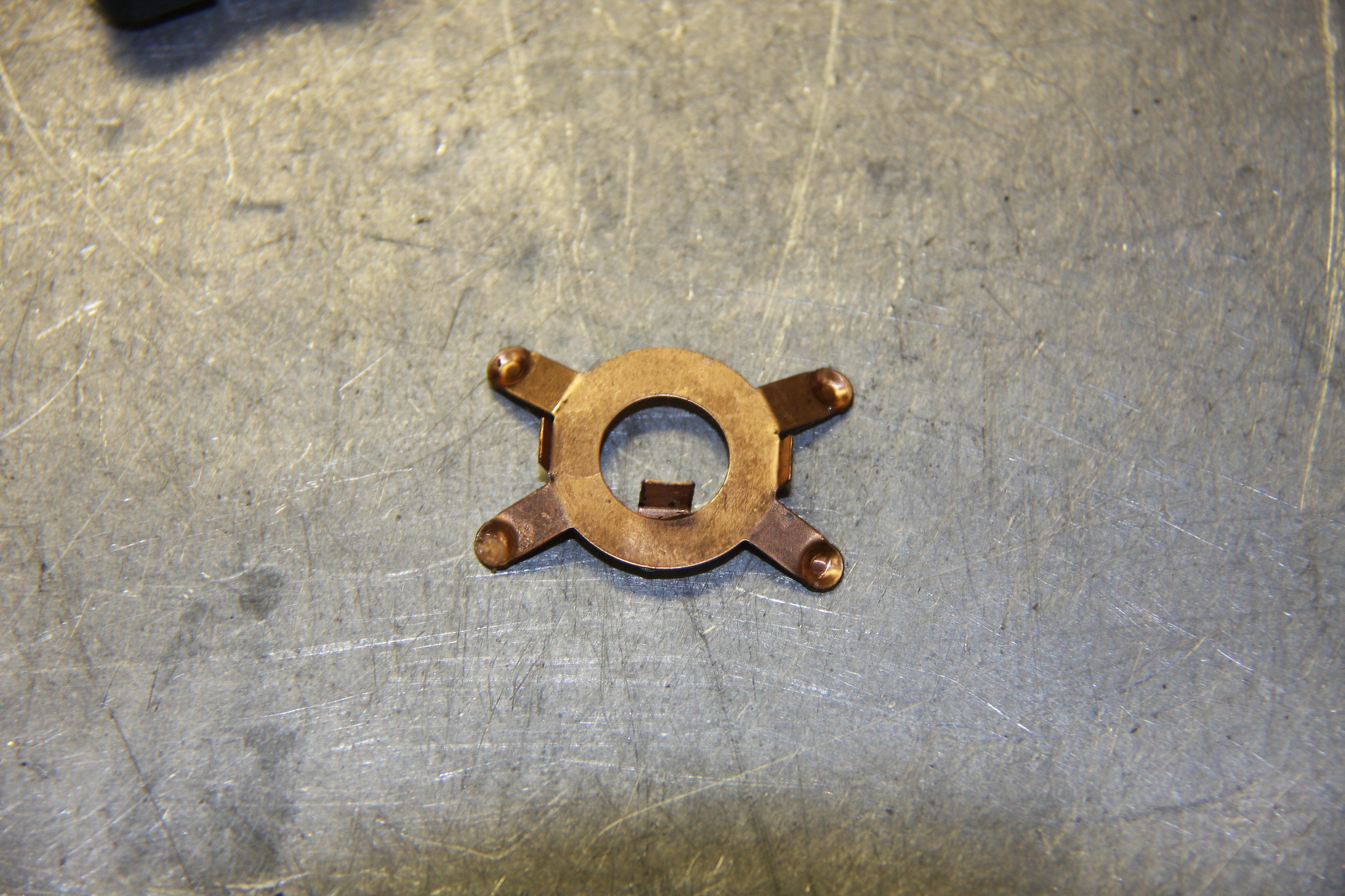
The internal ring controls the right/left turn signal function. As received, this ring has a wiper soldered
to it to ground to the wand shaft. The
ground wiper needs to be removed and the ID of the wiper opened up a bit to
prevent grounding to the wand shaft. I
did this with a Dremel tool sanding drum. Also make sure the location tabs are snug in the plastic mounting plate. Initially, I soldered a lead from this wiper to feed the
internal indicator lamp. This only works with the left/right turn functions and not with the four way flasher function. I used it this way until my 1 amp diodes arrived from Digikey. I used two of those diodes soldered directly to the yellow and green lamp leads with the married output feeding the internal indicator lamp (which I also replaced with a T 1 3/4 LED in a PVC holder with the black ground wire run direct to the LED). After a good slathering of dielectric grease and reassembly
the unit works perfect. Was it worth the
effort? Probably not. Another lesson why you should not buy ANY parts for an old Jeep on-line without finding out who actually builds them. How something like this makes it through the
engineering/design, manufacturing process, and retail being completely
non-functional is completely beyond comprehension. The only way I can see this unit actually
functioning as received is to run dedicated grounds to all four turn signal
lamps (completely isolated lamp sockets) with the positive leads to the lamps
wired direct to the fuse. Then running
those ground wires back to the unit.
Downside? Besides swapping out all
the lamp units, there will still be an internal short with the correctly wired
brake light switch lead and the wand would then be hot. The latter may make for some interesting
driving experiences. If you do or have purchased this unit MOST DEFIANTLY assemble the entire system on the garage/shop floor and test it with a 12 volt DC power supply. That may save you a lot of wasted time. Edited by duffer - 25 June 2019 at 2:17am |
|
|
1955 3B: 441sbc,AGE 4 speed transmission, Teralow D18w/Warn OD, 4.11:1 D44's/ARB's, glass tub & fenders, aluminum hood/grill, 8274, York OBA, Premier Power Welder; 67 CJ5: 225,T86AA, D18, 4.88's, OD
|
|
 |
|
|
CJ2A-CT
Member

Joined: 19 Apr. 2016 Location: Connecticut Status: Offline Points: 360 |
Post Options
Thanks(0)
Quote Reply
Posted: 25 June 2019 at 2:44am |
|
Very good post, thanks
|
|
|
46 CJ2a 22786 Brer Rabbit, 53 Willys Wagon, 62 Willys Pickup building with son-in-law, Jason
|
|
|
|
|
Rus Curtis
Member
Joined: 25 Mar. 2010 Location: Alabama Status: Offline Points: 1733 |
Post Options
Thanks(0)
Quote Reply
Posted: 25 June 2019 at 2:16pm |
|
Now that's a product review!
|
|
|
Rus Curtis
Alabama 1954 CJ3B Bantam T3-C |
|
|
|
|
Dogsbody
Member
Joined: 14 May 2019 Location: Portland Status: Offline Points: 35 |
Post Options
Thanks(0)
Quote Reply
Posted: 20 Sep. 2019 at 7:10pm |
|
Not to throw rocks, but I had no problem with the one I installed on my Jeep. When I got my CJ2A the turn signals didn't work. There were multiple issues- bad wiring, bad grounds, corrosion etc. I rewired the fronts and used a set of LED trailer lights in the rear. I used the harness a that came with the trailer lights for the rear harness. It was all just to get me going and legal.
They are bright, visible, and waterproof. I installed the Omix/ADA turn signal switch kit that I bought from KW. It installed easily and worked fine right out of the box. The instructions were clear and easy to follow. It took a couple of hours to do it. I don't know if there was a difference in the production of a couple of years ago but mine continues to work fine. Cheers, Dave
|
|
|
|
|
cpt logger
Member
Joined: 23 Sep. 2012 Location: Western Colorad Status: Offline Points: 3039 |
Post Options
Thanks(0)
Quote Reply
Posted: 20 Sep. 2019 at 8:23pm |
|
Duffer, the one you got was made for a Triumph, or any early British car, with electrical systems made by Joseph Lucas Ltd, AKA "Lucas Power Darkness" or "Lucas, Lord of Darkness". "The only way I can see this unit actually
functioning as received is to run dedicated grounds to all four turn signal
lamps (completely isolated lamp sockets) with the positive leads to the lamps
wired direct to the fuse. Then running
those ground wires back to the unit." That is how the Triumphs came from the factory! The turn signals and all other systems were powered from the + side of the battery, sometimes through a fuse first, sometimes no fuse! The ground side was switched.  "Downside? Besides swapping out all
the lamp units, there will still be an internal short with the correctly wired
brake light switch lead and the wand would then be hot. The latter may make for some interesting
driving experiences." If the brake lights were wired like the turn signals it would work fine, & that is how Lucas did it. Now take that to any American garage, bring some popcorn. It could be entertaining! What a mess.
 |
|
|
|
|
Ol' Unreliable
Member

Joined: 25 Sep. 2016 Location: CO Springs CO Status: Offline Points: 4226 |
Post Options
Thanks(0)
Quote Reply
Posted: 21 Sep. 2019 at 5:00am |
|
British (Lucas) electrical systems were positive ground until the mid-'70s or so, as I recall. Right now I can't remember if my '74 Triumph Trident was that way or not.
|
|
|
There's a reason it's called Ol' Unreliable
|
|
|
|
|
Post Reply
|
|
| Tweet |
| Forum Jump | Forum Permissions You cannot post new topics in this forum You cannot reply to topics in this forum You cannot delete your posts in this forum You cannot edit your posts in this forum You cannot create polls in this forum You cannot vote in polls in this forum |


 Topic Options